Search. Or just try integrating....

Tuesday, February 21, 2017

28: Energy Stored in a Charge Configuration

INTRO:
Four point charges, A, B, C, and D, are placed at the corners of a square with side length L. Charges A, B, and C have charge + q, and D has charge − q. (see Figure 1) 

Throughout this problem, use k in place of 1/(4πϵ0).


Figure 1
Figure 2

-----------------------------------------------------------------------------------------------------
PART A:
If you calculate W, the amount of work it took to assemble this charge configuration if the point charges were initially infinitely far apart, you will find that the contribution for each charge is proportional to kq2/L. In the space provided, enter the numeric value that multiplies the above factor, in W.

SOLUTION:
We know that the work to assemble a charge configuration of two charges a distance r from each other is simply W = kq2/r
If we want to assemble three charges A, B, and C... you have to consider the distances between all of them
WABC = kq2/(rAB + rAC + rBC)
finally, to assemble four charges A, B, C, & D....
WABCD = kq2/(rAB + rAC + rAD + rBC + rBD + rCD)

Note, however, that this is for all positive charges. If there is a negative charge in there, you must subtract that distance rather than add it to the divisor. 

Considering a square charge configuration with sides L, such as in figure 1... A, B, & C are positive & D is negative
rAB = L
rAC = L√2
rAD = L (-)
rBC = L
rBD = L√2 (-)
rCD = L (-)

⇒ W = kq2/(L + L√2 + (-L) + L + (-L√2) + (-L)
⇒ ∴ W = 0 × (kq2/L)
-----------------------------------------------------------------------------------------------------
PART B:
Which of the following figures depicts a charge configuration that requires less work to assemble than the configuration in the problem introduction? Assume that all charges have the same magnitude q. (Figure 2)

SOLUTION:
working through each option... 

(a)
This one appears to be complicated at first, but really isn't if you consider trig. 
The positive charges are equidistant from each other at a distance of L. This means that the negative charge is as far away from them as half of the distance between one of the positive charges and the corresponding line opposite it. 
rAB = L
rAC = L
rAD = ½L⋅sin(60) (-)
rBC = L
rBD = ½L⋅sin(60) (-)
rCD = ½L⋅sin(60) (-)
Wa = kq2/(3L - (3/2)L⋅(0.866))
⇒ ∴ Wa = (1/1.7) × (kq2/L) = (0.5879)× (kq2/L)

(b)
rAB = L
rAC = 2L
rAD = 3L (-)
rBC = L
rBD = 2L (-)
rCD = L (-)

Wb = kq2/(4L - 6L)
⇒ ∴ Wb = (-1/2) × (kq2/L) = (-0.5)× (kq2/L)

(c)
This one is identical to the problem introduction problem, but multiplied by a factor of 2. The factor doesn't matter, so Wc = 0 × (kq2/L)

In this case, the greater work is actually the less work. By this I mean, the positive work represents the amount of work the system actually exhibits, that we don't have to do. If there is negative work, we have to make up that work in order to place the charges as desired. 
Therefore, charge configuration (a) requires the least amount of work.

figure a

28: Problem 28.2

INTRO:
The electric field strength is 2.50×10⁴ N/C inside a parallel-plate capacitor with a 1.50 mm spacing. An electron is released from rest at the negative plate.

-----------------------------------------------------------------------------------------------------

PART A:
What is the electron's speed when it reaches the positive plate?
Express your answer with the appropriate units.

SOLUTION:
Givens / conversions:
E = 2.50×10⁴ N/C 
d =1.50 mm = 0.0015 m

we also need to know the properties of an electron
qe = -1.60×10⁻¹⁹ C
me = 9.11×10⁻³¹ kg

Using the energy equations:
ΔPE = Uf - Ui = qEd2 - qEd1
since it goes from x = d to x = 0,
ΔPE = qEd​

ΔKE = Kf - Ki = ½m(vf2 - vi2)
since we know that it starts at rest... 
ΔKE = ½mvf2

ΣEnergy = 0: ΔPE + ΔKE = 0
qEd + ½mvf2 = 0

now solve for vf... 
vf = [-2qEd/m]½

plug in values... 
vf = [-2(-1.60×10⁻¹⁹ C)⋅(2.50×10⁴ N/C )⋅(0.0015 m)/(9.11×10-31kg)]½
⇒ ∴ vf =​ 3.629×10⁶ m/s
vf =​ 3.63×10⁶ m/s
-----------------------------------------------------------------------------------------------------

28: PhET Tutorial: Charges and Electric Potential

INTRO:
Learning Goal:
To understand the spatial distribution of the electric potential for a variety of simple charge configurations, and to understand how the electric field and electric potential (voltage) are related.
For this problem, use the PhET simulation Charges and Fields. This simulation allows you to place multiple positive and negative point-charges in any configuration and look at the resulting electric field and corresponding electric potential.

[ SIMULATION ]

-----------------------------------------------------------------------------------------------------
PART A:
The electric potential (voltage) at a specific location is equal to the potential energy per unit charge a charged object would have if it were at that location. If the zero point of the voltage is at infinity, the numerical value of the voltage is equal to the numerical value of work done to bring in a unit charge from infinity to that location.
Select Show numbers and grid in the green menu, and drag one positive charge to the middle of the screen, right on top of two intersecting bold grid lines.
Using the voltage meter, you should find that 1 m away from the charge, the voltage is 9 V.  What is the voltage 2 m away from the charge?


Express your answer numerically in volts to two significant figures.

SOLUTION:
Unlike the magnitude of the electric field, the electric potential (voltage) is not proportional to the inverse of the distance squared.

4.5 V

-----------------------------------------------------------------------------------------------------

PART B:
What is the voltage 3 m away from the charge?

- 3 V
- 9 V
- 1 V

SOLUTION:
3 V

NOTE: 
Based on this result, and the previous question, the electric potential (voltage) is inversely proportional to the distance r from the charge: V∝1/r. Recall that the magnitude of the electric field E∝1/r2.
-----------------------------------------------------------------------------------------------------
PART C:
Another way to study voltage and its relationship to electric field is by producing equipotential lines. Just like every point on a contour line has the same elevation in a topographical map, every point on an equipotential line has the same voltage.
Click plot on the voltage tool to produce an equipotential line. Produce many equipotential lines by clicking plot as you move the tool around.  You should produce a graph that looks similar to the one shown below.

Place several E-Field Sensors at a few points on different equipotential lines, and look at the relationship between the electric field and the equipotential lines. Which statement is true?

- At any point, the electric field is parallel to the equipotential line at that point.
- At any point, the electric field is perpendicular to the equipotential line at that point, and it is directed toward lines of lower voltages.
At any point, the electric field is perpendicular to the equipotential line at that point, and it is directed toward lines of higher voltages.

SOLUTION:
The second option is true,
At any point, the electric field is perpendicular to the equipotential line at that point, and it is directed toward lines of lower voltages.

NOTE:
All points on an equipotential line have the same voltage; thus, no work would be done in moving a test charge along an equipotential line. No work is done because the electric field, and thus the force on the test charge, is perpendicular to the displacement of the test charge being moved along the equipotential line.
-----------------------------------------------------------------------------------------------------
PART D:
Equipotential lines are usually shown in a manner similar to topographical contour lines, in which the difference in the value of consecutive lines is constant. Clear the equipotential lines using the Clear button on the voltage tool. Place the first equipotential line 1 m away from the charge. It should have a value of roughly 9 V. Now, produce several additional equipotential lines, increasing and decreasing by an interval of 3 V (e.g., one  with 12 V, one with 15 V, and one with 6 V). Don’t worry about getting these exact values. You can be off by a few tenths of a volt.Which statement best describes the distribution of the equipotential lines?

The equipotential lines are closer together in regions where the electric field is stronger.
The equipotential lines are closer together in regions where the electric field is weaker.
The equipotential lines are equally spaced. The distance between each line is the same for all adjacent lines.

SOLUTION:
The first option is the correct one

The equipotential lines are equally spaced. The distance between each line is the same for all adjacent lines.

*UPDATE 07/26/2017 @ Andrea S.*
If you look closely, you can see that the first option is ACTUALLY: 
The equipotential lines are closer together in regions where the electric field is stronger


NOTE:
Near the positive charge, where the electric field is strong, the voltage lines are close to each other.  Farther from the charge, the electric field is weaker and the lines are farther apart.

-----------------------------------------------------------------------------------------------------
PART E:
Now, remove the positive charge by dragging it back to the basket, and drag one negative charge toward the middle of the screen. Determine how the voltage is different from that of the positive charge.How does the voltage differ from that of the positive charge?

The voltages are positive, but the magnitude increases with increasing distance.
The voltage distribution does not change.
The voltages become negative instead of positive and keep the same magnitudes.

SOLUTION:
The third option is true
The voltages become negative instead of positive and keep the same magnitudes.

NOTE:
The voltage is still inversely proportional to the distance from the charge, but the voltage is negative everywhere rather than positive.
-----------------------------------------------------------------------------------------------------
PART F:
Now, remove the negative charge, and drag two positive charges, placing them 1 m apart, as shown below.

What is the voltage at the midpoint of the two charges?
Exactly twice the voltage produced by only one of the charges at the same point
- Zero
Greater than zero, but less than twice the voltage produced by only one of the charges at the same point

SOLUTION:
The first one is correct
Exactly twice the voltage produced by only one of the charges at the same point

NOTE:
Because voltage is a scalar quantity, there are no vector components with opposite directions canceling out, as for electric fields. The voltage is simply the sum of the voltages due to each of the individual charges. Since both charges are positive, the voltage due to each charge (at all locations) is positive.
-----------------------------------------------------------------------------------------------------
PART G:
Now, make an electric dipole by replacing one of the positive charges with a  negative charge, so the final configuration looks like the figure shown below.

What is the voltage at the midpoint of the dipole?

The voltage at the midpoint of the dipole is...

- positive
- zero
- negative

SOLUTION:
The voltage at the midpoint is zero

NOTE:
Because the voltage due to the negative charge has the opposite sign of the voltage due to the positive charge at the midpoint, the net voltage is zero. The electric field, however, is not zero here!-----------------------------------------------------------------------------------------------------
PART H:
Make several equipotential lines similar to the figure below.

Try to have the equipotential lines equally spaced in voltage. Then, use an E-Field Sensor to measure the electric field at a few points while looking at the relationship between the electric field and the equipotential lines.
Which of the following statements is true?

- The electric field strength is greatest where the equipotential lines are very close to each other.
- The electric field strength is greatest where the voltage is the smallest.
- The electric field strength is greatest where the voltage is the greatest.

SOLUTION:
The first option is correct
The electric field strength is greatest where the equipotential lines are very close to each other.

HINT:
Locations where the voltage is changing steeply are locations with a strong electric field. The magnitude of the electric field is equal to the rate the voltage is changing with distance. Mathematically, this idea is conveyed by |Es|=dV/ds, where Es is the component of the electric field in the direction of a small displacement ds. (As you learned earlier, the electric field is directed in the direction where the voltage decreases.)

Tuesday, February 7, 2017

27: Problem 27.50

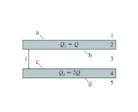
INTRO:(Figure 1) shows two very large slabs of metal that are parallel and distance l apart. The top and bottom surface of each slab has surface area A. The thickness of each slab is so small in comparison to its lateral dimensions that the surface area around the sides is negligible. Metal 1 has total charge Q1=Q and metal 2 has total charge Q2=2Q. Assume Q is positive.
Figure 1
-----------------------------------------------------------------------------------------------------
PART A:
Determine the electric field strength E1 in region 1. Give your answer as a multiple of Q/ε0.
Express your answer in terms of some or all of the variables l, A, Q, and the constant π.

SOLUTION:
One Gaussian surface is a cylinder with end-area a extending past the two metal slabs. A second Gaussian surface ends in region 3, the space between the slabs

Using Gauss's Law, ∫E⋅dA = ∫top E⋅dA + ∫bottom E⋅dA + ∫sides E⋅dA = E1a + E5a + 0 = Qin / ε0

The total charge per unit area on both surfaces of the top slab is Q1/A = Q/A, so the charge enclosed within the cylinder is Qa/A.

Similarly, the enclosed charge on the lower slab is Q2a/A = 2Qa/A

Thus, E1a + E5a = Qa/(A⋅ε0) + 2Qa/(A⋅ε0) = 3Qa/(A⋅ε0)
∴ E1 + E5 = 3Q/(A⋅ε0)

Fields E1 & E5 are both a superposition of the fields of four sheets of surface charge. Because the field of a plane of charge is independent of distance from the plane, the superposition at points above the top plane must be the same magnitude, but opposite direction, as the superposition at points below the bottom plane. 

∴ E1 = E5 = 1/2(3Q/(A⋅ε0))

E1 = 3/2A Q/ε0

-----------------------------------------------------------------------------------------------------

PART B:
Determine the electric field strength E2 in region 2. Give your answer as a multiple of Q/ε0.
Express your answer in terms of some or all of the variables l, A, Q, and the constant π.

SOLUTION:
Because these are metals we immediately know that EE4 = 0
0

-----------------------------------------------------------------------------------------------------

PART C:
Determine the electric field strength E3 in region 3. Give your answer as a multiple of Q/ε0.
Express your answer in terms of some or all of the variables l, A, Q, and the constant π.

SOLUTION:
Consider the Gaussian surface on the right. The lower slab is more positive than the upper slab, so the electric field in region 3 must point upward, into the lower face of this cylinder.

∫E⋅dA = ∫top E⋅dA + ∫bottom E⋅dA + ∫sides E⋅dA = E1a - E3a + 0 = Qin / ε0
where the minus sign with E3 is because of the direction.  We know E1, and we've already determined Qin = Qa/A.

Thus, E3 = E1 - Q/(A⋅ε0) = 3Q/(2A⋅ε0) - Q/(A⋅ε0
∴ E3 = Q/(2A⋅ε0)

E3 = 1/2A Q/ε0

-----------------------------------------------------------------------------------------------------
PART D:
Determine the electric field strength E4 in region 4. Give your answer as a multiple of Q/ε0.
Express your answer in terms of some or all of the variables l, A, Q, and the constant π.

SOLUTION:
See part B
0

-----------------------------------------------------------------------------------------------------

PART E:
Determine the electric field strength E5 in region 5. Give your answer as a multiple of Q/ε0.
Express your answer in terms of some or all of the variables l, A, Q, and the constant π.

SOLUTION:
See Part A
E5 = 3/2A Q/ε0

-----------------------------------------------------------------------------------------------------
PART F:
Determine the surface charge density ηa on the surface a. Give your answer as a multiple of Q/A.

SOLUTION:
The electric field at the surface of a conductor is E = η/ε0
We can use the known fields and η = ε0E to find the four surface charge densities.  
At surface a, E1 points away from the surface, Thus
ηa  ε0E1 ε03Q/(2A⋅ε03Q/(2A)

ηa 3/2Q/A

-----------------------------------------------------------------------------------------------------

PART G:
Determine the surface charge density ηb on the surface b. Give your answer as a multiple of Q/A.

SOLUTION:
At surface b, E3 points toward the surface, Thus
ηb  -ε0E1 = -ε0Q/(2A⋅ε0= -Q/(2A)

ηb = -1/2Q/A

-----------------------------------------------------------------------------------------------------

PART H:
Determine the surface charge density ηc on the surface c. Give your answer as a multiple of Q/A.

SOLUTION:
Surface c is opposite to surface b, because the field points away from the surface.
Therefore, ηc = - ηb Q/(2A)

ηc 1/2Q/A

-----------------------------------------------------------------------------------------------------

PART I:
Determine the surface charge density ηd on the surface d. Give your answer as a multiple of Q/A.

SOLUTION:
At surface d, the field points away from the surface and has the same strength as E1
Therefore, ηd = ηa = 3Q/(2A)

ηd 3/2Q/A
-----------------------------------------------------------------------------------------------------